Build Your Own Hand Truck!

This is a step by step guide to fabricating a heavy duty hand truck that will last a life time. I hope you find them valuable for your personal or business use! If you do please share this page or let me know (I love getting nice emails).
MATERIALS REQUIRED:
- 28 feet of steel tubing (round): ¾ inch in diameter X 16 Gauge.
- 2 inches of steel tubing (round): 7/8 inch in diameter X 16 Gauge.
- Mild steel plate: ¼ inch x 21 inches x 18 inches.
- 18.5 inch steel bar (round): 5/8 inch in diameter.
- 2 steel rimmed rubber tires: 8 inches in diameter x 2 inches wide, with an offset rim.
- 4 SAE Washers: 5/8 inch.
- 2 cotter pins: 1/8 inch x 1.25 inch. Or you can use spring rolls (see below).
Scrap wood or 1 inch x 2 inch pine wood or something similar.
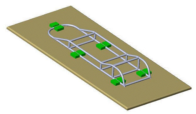
Hand Truck Assembly Illustration:


Weldments Illustration:
 |
 |

How To Build This Heavy Duty Hand Truck In 22 Easy Steps:
For most fabricators these steps and images alone should be just fine for this build. But you can get a one page blue print of the weldments (metalwork) here if you want more detail. Or, you can get the entire 14 page set of plans with detailed steps and blue prints for this hand truck here.
Refer to the part numbers on the parts list under the hand truck assembly and weldments images above.
Step 1: Make part number WP-904-2 by cutting a length of ¾” x 16 GA tubing to length. Using a tube bender with a ¾” x 4 ½” radius die, make the bends in part number WP-904-2 as shown on the drawing.
NOTE: Whenever you make more than one bend in a tube form that must remain flat, pay particular attention to the plane of the tube prior to each bend. Otherwise, the tube form may become unusable. This can be accomplished by adjusting the height of a take-up table or surface to
correspond to the bottom of the tube. This is best done before any bends are made, while the tube is resting in the bending die.
Step 2: Add the miter cuts to the both ends, as shown on drawing number WP-904. Make sure that both cuts are parallel to each other and perpendicular to the plane of the bent tube form.
Step 3: Create part number WP-904-3 by cutting a length of ¾” x 16 GA tubing an inch or two longer than the cut length listed on the drawing (table on pg 2). Using a tube bender with a ¾” x 4 ½” radius bending die, create the bends as shown on the drawing. As noted above, pay close attention to the plane of the tube as it is bent. Also make sure you measure the length of each straight leg and the degrees of each bend as you bend them.
Step 4: Cut WP-904-3 to the final, listed length or dimension after the bends are complete and make the final cuts to the ends of the tube using a hole saw tool such as a “Joint Jigger”™ or similar brand. Make the angled ¾” diameter cut at the top end of the tube form and the miter cut at the bottom.
If your particular hole saw tool will not make the shallow cut at the top of the part, an alternate method is to form it with a bench grinder. This is a common method of creating a “Fish-mouth” in the ends of tubing used in aircraft construction.
It is done by using a dressing wheel to shape a grinding wheel to have a ¾” radius. Then, by holding the end of a tube at the correct angle to the grinder, a fish-mouth can be created for a tight fitting joint. Be sure to work slowly and check the fit often. After a while, you will get a feel for how much to grind. The results can be surprisingly good.
Step 5: With the hole saw tool, cut part numbers WP-904-5, WP-904-6, WP-904-7, and WP-904-8.
Step 6: Using scrap wood, make several wood blocks, approximately
2” x 3” x 1” thick.
Step 7: Lay part number WP-904-2 of the hand truck on a flat (wood) work table, with the legs parallel to the edge of the table. Place two wood blocks on either side of each leg of the part.
Note: the legs of this part should be parallel. Fasten the blocks to the table top using 1 ½ “ wood screws. This is in effect a welding
jig to hold the parts in place while welding.
Step 8: Position part numbers WP-904-3, WP-904-7, and WP-904-8 as indicated on the drawing and shown below.

Step 9: Ensure the parts are perpendicular to the table top. This can be done using a carpenters’ square. Tack weld each joint.
Step 10: Build the other side of the hand truck frame in like manner.

Step 11: Fit part numbers WP-904-5 and WP-904-6’s into the frame as indicated on the drawing. Tack weld them in place at the joints.
Step 13: Make sure the weldment remains flat to the table by clamping the legs of WP-904-2 to the table. Also, by alternately welding joints on either side of the frame will help keep distortion to a minimum.
Step 14: Begin welding each joint together as indicated on the drawing.
Step 15: Use a tube bender and hole saw tool to create the handle, part number WP-904-4. Refer to drawing for dimensions.
Step 16: Position the handle to the frame as indicated on the drawing and perpendicular to the table top. Tack weld in place at either end of the handle. Then final weld as indicated.
Step 17: Slide the axle rod, part number WP-904-11, through both WP-904-9’s. Position the WP-904-9 parts as indicated on the drawing and tack weld in place. Once you are sure they are positioned correctly, final weld per the drawing.

Step 18: Make the nose plate for the hand truck by forming the bend in WP-904-10 with a shop press, or press brake. Using a hand grinder, form the chamfer on the end of the part.

Step 19: Position part number WP-904-10 as indicated on the drawing and tack weld in place on either side of the part. Then, final weld as indicated.
Step 20: Paint or powder coat as desired.
Step 21: Attach the wheels to the axle with a 5/8” washer both sides of the wheel. Fix the wheel in place using the listed cotter pin. A 1/8” roll spring pin could be used in place of the cotter pin for a semi-permanent attachment.


Step 22: Put it to work! That’s what it was designed for.
Related Guides:
Copyright WcWelding.com All Rights Reserved.


Welding Plans:

New! Welding Table
New! Log Splitter
Top Projects: