How To Build A Manual Log Splitter Step By Step!

It's highly recommended that you get the actual plans for this manual log splitter in order to following along with this guide on how to assemble it.
An experienced fabricator could use this guide alone but having the plans to refer is probably a good idea. If you have any questions on this guide to building this log splitter please contact us and we will answer any question you have on it.
Machinery and Tools Required For The Log Splitter Assembly:
- Chop saw or Angle grinder.
- Drill press.
- MIG, TIG or Arc Welding.
- Welding equipment.
- Fitter’s vise.
- Hammer, wrench set and tape measure.
- Drill set.
- Plasma Cutter (recommended).
- Universal or CNC Lathe (recommended).
- Universal or CNC Milling machine (recommended).
Manual Log Splitter Build Materials List:
- Mild steel square tube – 2 X 2’’ (19 in).
- Rectangular A633 Steel bar – 1 X 2 ½’’ (10 in).
- A284 steel sheet – 0.5’’ thickness (22 ft2); 0.25’’ thickness (53 ft2).
- 2’’ A284 steel round bar (0.5 in); 1 ½’’ A284 steel round bar (12 in); ½’’ A284 steel round bar (20 in).
- L-profile A284 steel – 7x4x0.5’’ (11.5 ft).
- 10’’ NPS pipe (4 in).
- (4) Screw 7/16-14x1 UNC.
- (2) Washer ANSI FW 0.75.
- (4) Washer ANSI LW 0.4375.
- (1) Clevis pin 0.75 X 10.5’’.
- (1) Clevis pin 0.75 X 3’’.
- (2) Cotter pin 0.16 X 1.5’’.
- (1) Long ram double position hydraulic jack T30808.
- (1) Spring LE207P08S.
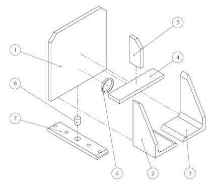
1. Log Splitter Assembly:
Parts:
1. Axe.
2. Wall.
3. Partition.
4. Sidewall.
5. Cap.
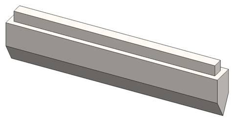
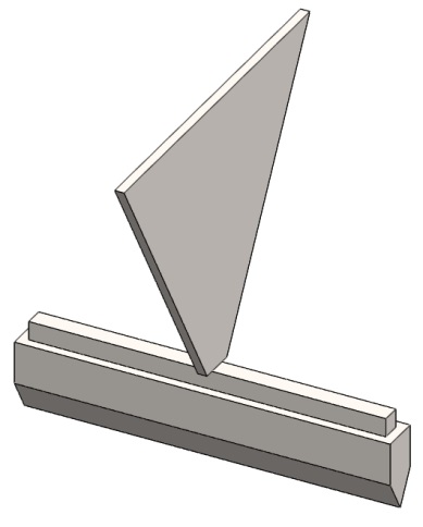
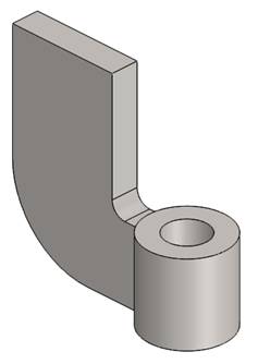
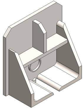
Step 1: Cut a 10’’ work piece of 1 X 2 ½’’ steel bar. Mill the 60º cone and 0.25’’ lowering according to drawing LS8-1.3 W.
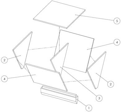
Step 2: Cut the Partition piece according to drawing LS8-1.3 W. Clamp the Axe in vice on the long side surface. Position the Partition in the middle of the Axe and upright as shown on the picture. Hold with one hand or use welding fixtures if available. Tack weld them in place.
Step 3: Cut the two side walls of 0.25’’ thick A284 steel sheet (see drawing LS8-1.3 W). Position one of the pieces as shown on the drawing and tack weld in place. Proceed to second piece. (NOTE: Don’t complete the welds yet).
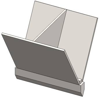
Step 4: Cut the Cap according to drawing LS8-1.3 W. Position it in between the Side Walls and over the Partition as shown on the picture and tack weld in place.
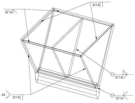
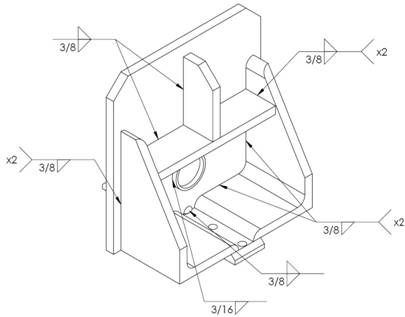
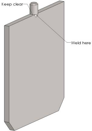
Step 5: Check alignment of all the components and if there is no gaps complete the inner welds according to the welding plan (Fig. 1.1).
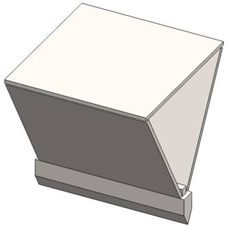
Step 6: Cut the two wall pieces of 0.25’’ A284 steel sheet observing the dimensions on the drawing. Align them with the side walls and tack weld.
Step 7: Check alignment again and complete all of the outer welds observing the welding plan (Fig.1.1).
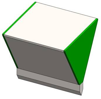
Step 8: The welds must be finely filed as the Splitter has to be aligned with the L profile.
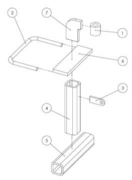
2. Foot Frame Assembly.
Parts:
1. Nut.
2. Handle.
3. Support spring.
4. Foot.
5. Base.
6. Board support.
7. Rib.
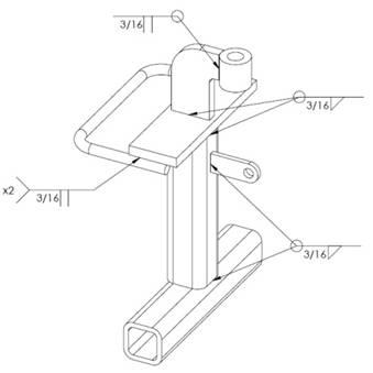
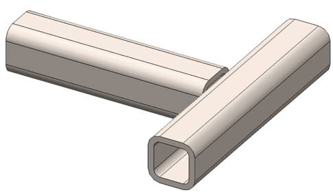
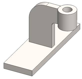
Step 1: Cut two pieces of mild steel square tube with the corresponding length (see drawing LS8-1.4). Lay the parts out on a flat work surface and weld them together according to the welding plan (Fig. 2.1).
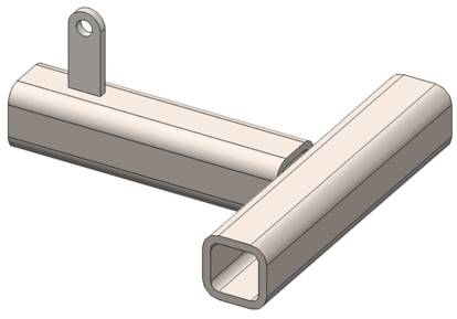
Step 2: Cut 1 x 2.5’’ piece of A284 steel sheet and drill the 0.5’’ hole. Position the part according to drawing and complete the weld.
Step 3: Cut 1.5’’ work piece of 1 ½’’ A284 steel round bar. Turn it on a universal or CNC lathe. Cut 2.5 x 3.688’’ work piece of 0.5’’ A284 steel sheet and shape the overall dimensions according to drawing LS8-1.4. Position the parts upside down on a flat working surface and weld them together.
Step 4: Cut 2.5 x 8’’ piece of A284 steel sheet. Position the part on a flat surface and weld the Rib right in the middle.
Step 5: Cut 20’’ piece of ½’’ A284 steel round bar. Execute the bends according to the drawing. Weld to Board support as shown in montage plan (Fig. 2.2).
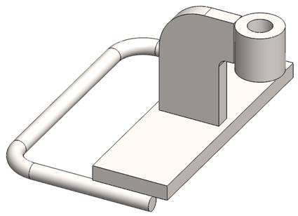
Step 6: Weld the assemblies from previous steps together observing the welding plan (Fig. 2.1). (NOTE: Make sure the Nut and the Support spring are directed in one direction).

3. Pusher Assembly.
Parts:
1. Plate.
2. L profile.
3. R profile.
4. Rib.
5. Gusset.
6. Collar.
7. Damping plate.
8. Bolt.
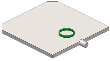
Step 1: Cut 10 x 10’’ piece of 0.5’’ A284 steel sheet. Machine the 1 x 45º chamfers using an angle grinder. Clamp in Vice upside down.
Step 2: Cut 1’’ work piece of 1 ½’’ A284 steel round bar. Machine the part according to drawing LS8-2.0 W. Position the Bolt in the middle of the Plate as shown in montage plan (Fig. 3.2).
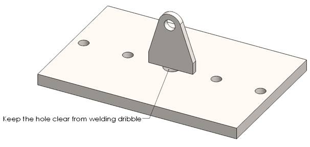
Step 3: Weld the parts from Step 1 and Step 2 together observing the welding plan (Fig. 3.1). Keep clear the surface of the Plate as the Damping plate will be to this surface.
Step 4: Cut 0.5’’ piece of 2’’ round bar or use tube with the same dimensions. Machine the part according to drawing LS8-2.0 W.
NOTE: The dimensions and position of the Collar may vary, depending on the Jack that you bought.
Step 5: Lay the Plate on a flat working surface. Check the right position of the Collar and complete the welds according to the welding plan (Fig. 3.1).
Step 6: Cut 2 x 10’’ and 2 x 4’’ pieces of 0.5’’ A284 steel sheet according to the drawing. Position the parts observing the dimensions on the drawing and complete the welds.
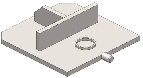
Cut two 4’’ long pieces of 7 x 4’’ A284 steel L-profile. Machine the chamfers according to the drawing. Position the parts observing the montage plan (Fig. 3.2) and complete the welds according to the welding plan (Fig. 3.1).
Step 8: Cut 2 x 8’’ piece of 0.5’’ A284 steel sheet. Drill the holes observing the dimensions on the drawing and machine the chamfers. Thread the Damping plate on the Bolt.
4. Assembling The Bottom Plate Of The Manual Log Splitter.
Parts:
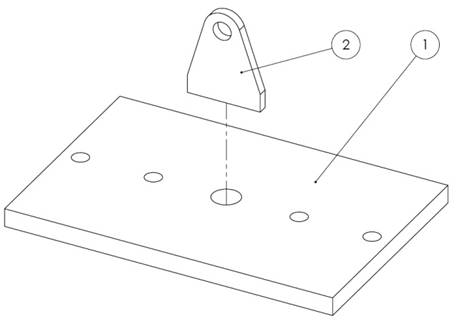
1. Plate.
2. Spring support.
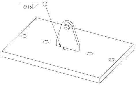
Step 1: Cut 6 x 9’’ piece of 0.5’’ A284 steel sheet. Drill the holes observing the dimensions on drawing LS8-3.0W. Lay the part out on a flat working surface.
Step 2: Cut 2 x 2.5’’ piece of 0.5’’ A284 steel sheet. Shape according to drawing and drill the 0.5 hole.
Step 3: Lay the plate on a flat working surface. Position the Spring support in the middle of the plate and tack weld in place. Check alignment and complete the welds according to the welding plan (Fig. 4.1).
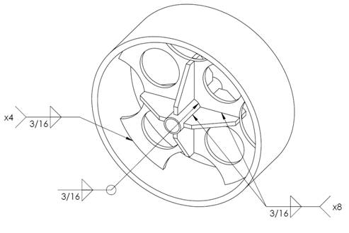
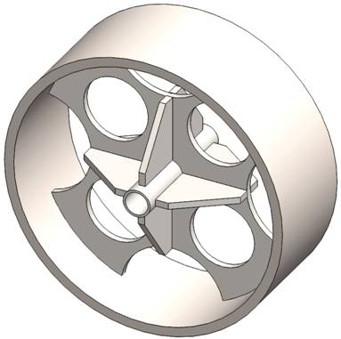
5. Wheel Assembly.
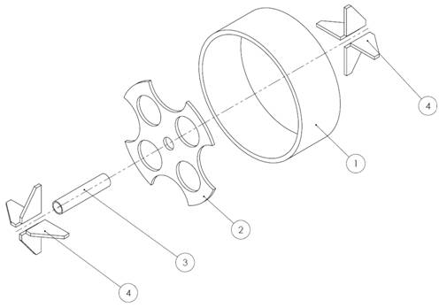
Parts:
1 Rim.
2. Diaphragm.
3. Hub.
4. Gusset.
Step 1: Cut 10 x 10’’ work piece of 0.25’’ A284 steel sheet. Machine the part according to drawing LS8-4.0W.
Step 2: Cut 5’’ work piece of 1 ½’’ A284 steel round bar. Turn it on a universal or CNC lathe. Thread the Hub through the center hole of the Diaphragm. Make sure the Hub is threaded exactly by its half. Complete the welds according to the welding plan (Fig. 5.1).
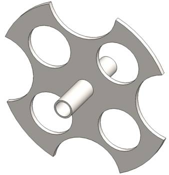
Step 3: Cut eight 2 x 2.5’’ work pieces of 0.25’’ A284 steel sheet and machine the chamfers. Position the Gussets one by one as shown in the drawing and montage plan (Fig. 5.2). Tack weld them in place and proceed to the other side. Check alignment and complete the welds according to the welding plan.
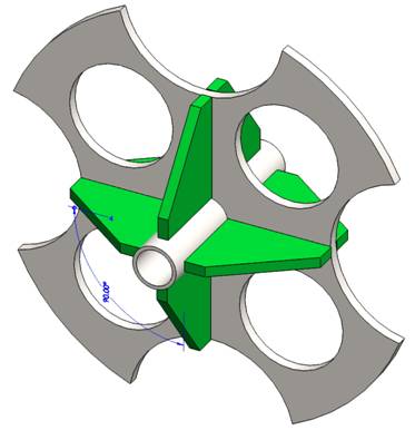
Step 4: Cut 4’’ piece of 10’’ NPS pipe. Position the assembly from the previous steps in the middle of the inner diameter. Tack weld in four spots. Check the alignment the outer diameter of the pipe and the inner diameter of the Hub. If alignment is normal proceed to welding the parts observing the welding plan (Fig. 5.1).
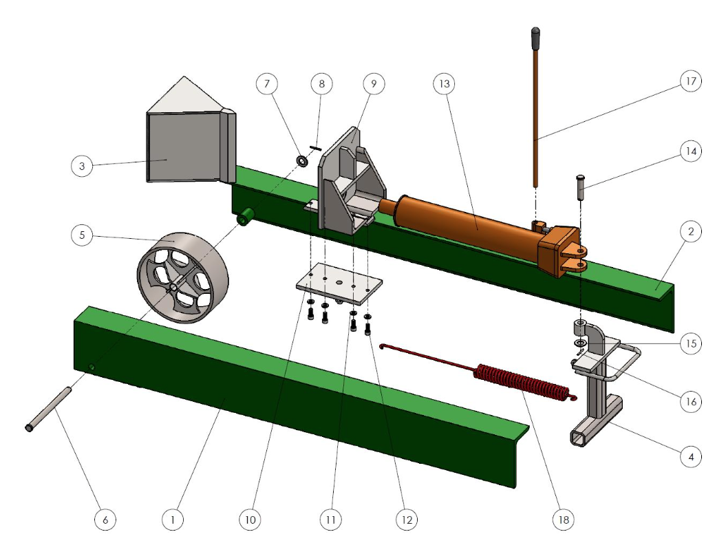
6. Entire Manual Log Splitter Assembly.
Parts:
- L girder frame 7x4x0.5 (LS8-1.1).
- R girder frame 7x4x0.5 (LS8-1.2).
- Splitter (LS8-1.3 W).
- Foot frame (LS8-1.4 W).
- Wheel (LS8-4.0W).
- Clevis pin 0.75 X 10.5’’.
- Washer ANSI FW 0.75.
- Cotter pin 0.16 X 1.5’’.
- Pusher (LS8-2.0 W).
- Bottom plate (LS8-3.0W).
- Washer ANSI LW 0.4375.
- Screw 7/16-14x1 UNC.
- Hydraulic Jack.
- Clevis pin 0.75 X 3’’.
- Washer ANSI FW 0.75.
- Cotter pin 0.16 X 1.5’’.
- Handle.
- Spring.
Step 1: Stake on the Left (1) and Right girder (2) and align the walls with the Splitter assembly (3) according to drawing LS8-1.0. Use welding fixtures to prevent deformation of the elements during welding. Tack weld in a few spots.
Step 2: Position the Foot frame (4) as shown in drawing LS8-1.0 on the manual log splitter plans. Tack weld them in place.
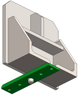
Step 3: Check alignment of the elements. You can try to slide the Damping plate in the slot formed by the L-profiles. It has to slide without retaining. If there is no gaps complete the welds of both elements.
Step 4: Position the Wheel (5) concentric to the bushings, already welded to the L-profiles, (see drawings LS8-1.1 and LS8-1.2) and thread the Clevis pin (6). Mount the Washer (7) and lock with Cotter pin (8).
Step 5: Take the Pusher assembly (9) and slide the Damping plate in the slot. Position the assembly about 20 inches from the Splitter. Mount the Bottom plate (10) using the Washers (11) and Screws (12).
Step 6: Proceed to mounting the Hydraulic Jack (13). Use the Clevis pin (14), Washer (15) and Cotter pin (16).
Step 7: Mount the Handle (17) and Spring (18). Make sure the Jack is aligned with the Collar on the Pusher.
Congratulations!
You finished assembling the manual log splitter. Now send us some pictures!


Welding Plans:

New! Welding Table
New! Log Splitter
Top Projects: