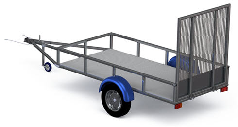
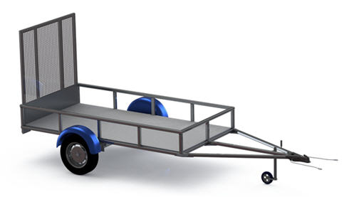
Utility Trailer Assembly Guide!
This utility trailer assembly tutorial provides you with the step by step directions you may need to complete the trailer from the plans that are available here.
The plans were designed for an intermediate level fabricator in mind. But even a beginner with the help of a metalworker, with proper safety training, can complete the build as well.
Machinery and Tools Required For The Utility Trailer Assembly:
1. Chop saw or Angle grinder.
2. Drill press.
3. MIG, TIG or Arc Welding.
4. Welding equipment.
5. Bending machine.
6. Fitter’s vise.
7. Hammer, wrench set and tape measure.
8. Drill set – 0.2’’ - 1’’.
9. Plasma cutter (recommended).
10. Universal or CNC lathe (recommended).
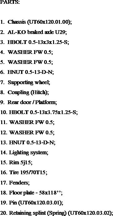
Materials Required:
1. Mild steel square tube – 2’’ X 2’’ t=0.12’’ (150 ft);
2. Mild steel sheet – 0.125’’ thickness (870 ft2). 0.25’’ thickness (19 ft2). 0.20’’ thickness (100 in2).
3. 1’’ steel round bar – (25 in).
4. (4) HBOLT 0.5-13x3x1.25-S.
5. (2) HBOLT 0.5-13x3.75x1.25-S.
6. (6) HNUT 0.5-13-D-N.
7. (12) WASHER FW 0.5.
8. (2) Retaining splint (Spring) 7/32 x 1’’ .
9. (1) AL-KO braked axle U29.
10. (1) Coupling (Hitch).
11. (1) Supporting wheel.
12. (2) Rim 5j15, offset 0.
13. (2) Tire 195/70T15.
14. (2) Fender.
15. (1) Electric and lighting system.
1. Assembling The Utility Trailer Chassis.
The assembling of Chassis will be discussed in two parts, because of the
its big size. In the third part will be discussed the assembly of all
chassis components.
1.1 Assembling lower frame:
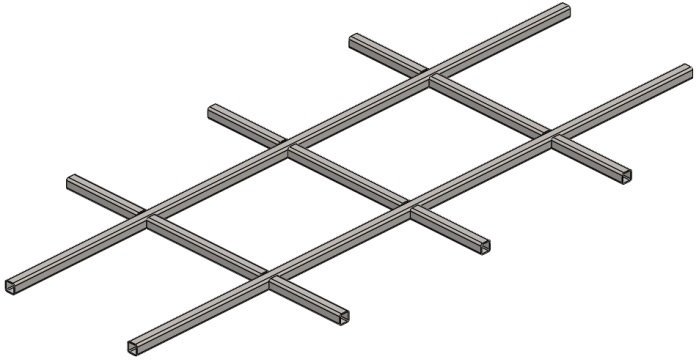
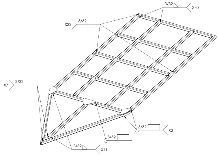 Fig. 1.1 Chassis lower frame welding plan
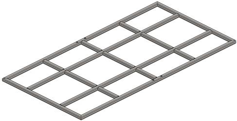
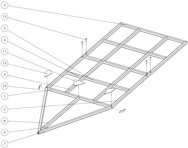 Fig. 1.2 Chassis lower frame montage plan.
Parts:
1. Front lower width beam (UT60x120.01.01).
2. Side lower length beam (UT60x120.01.02).
3. Rear element (UT60x120.01.18).
4. Inner length beam (UT60x120.01.03).
5. Crossmember middle (UT60x120.01.04).
6. Crossmember side (UT60x120.01.05).
7. Drawbar side element (UT60x120.01.06).
8. Drawbar middle element (UT60x120.01.07).
9. Coupling support (UT60x120.01.08).
10. Side reinforcement (UT60x120.01.13).
11. Middle lower reinforcement (UT60x120.01.14).
12. Side lower reinforcement (UT60x120.01.15).
13. Bushing (UT60x120.01.17).
Step 1: Cut
part numbers UT60x120.01.01, UT60x120.01.02 and UT60x120.01.18 with the
corresponding length and shape the ends at 45 degrees using an angle
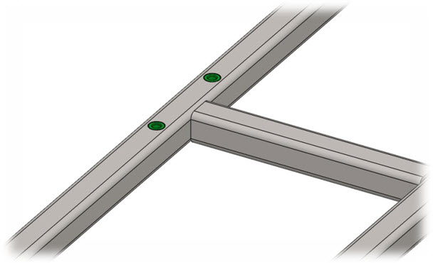
grinder. Drill the holes observing the dimensions on drawing
UT60x120.01.02. Lay the parts out on a flat work surface. Position them
as shown on the next figure and complete the welds according to the
welding plan (Fig. 1.1).
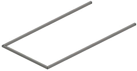
Step 2: Cut part numbers UT60x120.01.03, UT60x120.01.04 and UT60x120.05. Arrange them according to dimensions on drawing UT60x120.01.00. Tack weld them in place. Check alignment twice and complete the welds according to the welding plan (Fig. 1.1).
Step 3: Lay the parts out from Step 1 and Step 2 on a flat work surface. Position them observing the drawing UT60x120.01.00. Tack weld them in place. Check alignment and complete the welds according to the welding plan (Fig. 1.1).
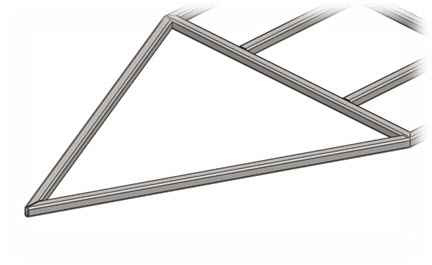
Step 4: Cut part number UT60x120.01.06 with the corresponding length and shape the ends according to drawing using an angle grinder. Position the parts, so that the corners are aligned and complete the welds.
Step 5: Cut part numbers UT60x120.01.07 and UT60x120.01.08 according to drawings. Position the parts and complete the welds observing the welding plan (Fig. 1.1).
 Step 4. Step 4. |
 Step 5. Step 5. |
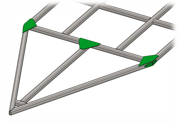
Step 6: Cut part number UT60x120.01.13 according to the blank on
drawing. Bend to 155º. Position the parts as shown on Fig. 1.2 and
complete the welds.
Step 7: Cut part numbers
UT60x120.01.14 and UT60x120.01.15 according to dimensions on drawings.
Position the parts, so the overall profiles have to be aligned to the
frame and complete the welds observing the welding plan (Fig. 1.1).
Step 8: Cut four 2’’ work pieces of 1’’ round bar. Turn it on a universal or CNC Lathe according to dimensions on drawing UT60x120.01.17. Put in the parts at the holes of side length beam and complete the welds.
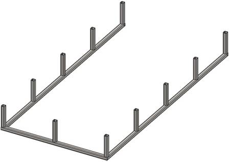
1.2 Assembling upper frame.
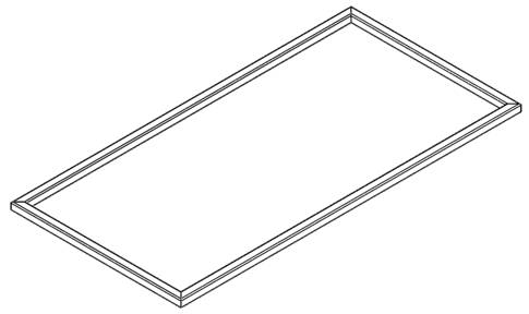
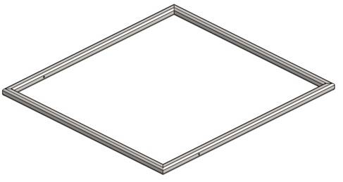
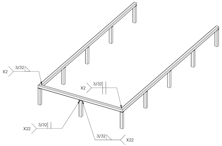 Fig. 1.3 Chassis upper frame welding plan.
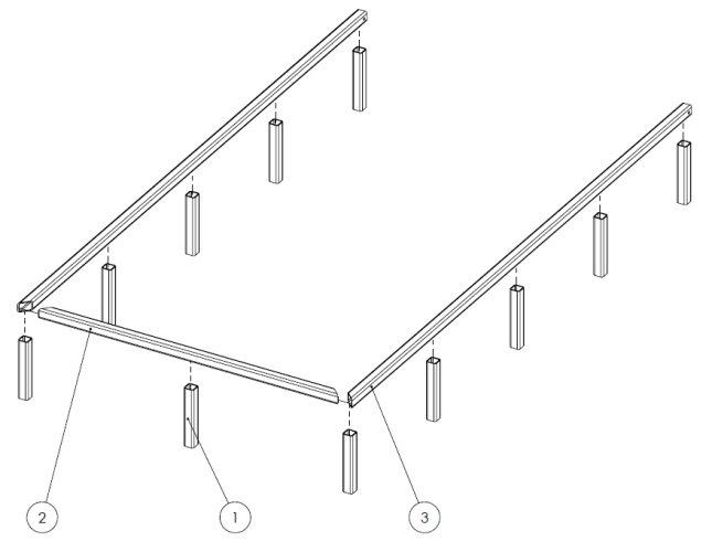 Fig. 1.4 Chassis upper frame montage plan.
Parts:
1. Vertical element (UT60x120.01.09).
2. Upper front width element (UT60x120.01.10).
3. Upper side length element (UT60x120.01.11).
Step 1: Cut
part numbers UT60x120.01.10 and UT60x120.01.11 with the corresponding
length and shape the ends at 45 degrees using an angle grinder. Drill
the holes observing the dimensions on drawing UT60x120.01.11. Lay the
parts out on a flat work surface. Position them as shown on the next
figure and complete the welds according to the welding plan (Fig. 1.3).
Step 2: Cut 11 pieces of part number UT60x120.01.09. Tack weld them in place one by one observing the dimensions on drawing UT60x120.01.00. Check alignment again and complete the welds according to the welding plan (Fig. 1.3).
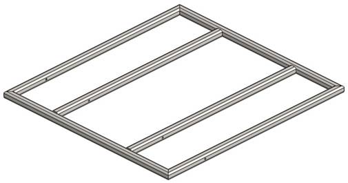
1.3 Assembling the complete chassis.
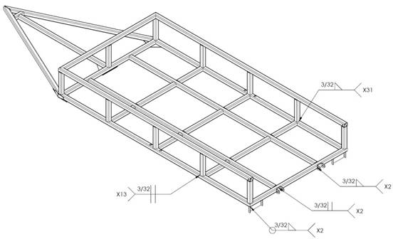 Fig. 1.5 Chassis welding plan.
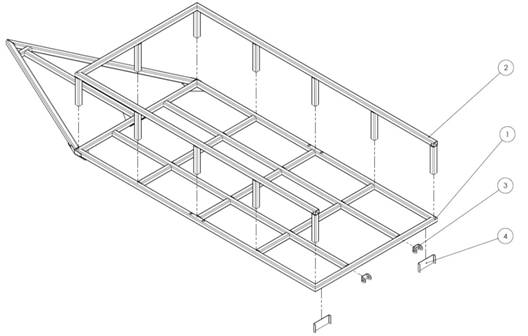 Fig. 1.6 Chassis montage plan.
Parts:
1. Lower frame assembly.
2. Upper frame assembly.
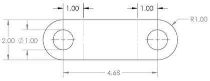
3. Hinge fixed element (UT60x120.01.16).
4. Lights support (UT60x120.01.12).
Step 1:
Lay the lower frame assembly (1) on a flat working surface, so the
reinforcements should be directed to the ground. Position the upper
frame assembly (2) according to montage plan (Fig. 1.6). Tack weld all
the connection spots. Check alignment and complete the welds according
to the welding plan (Fig. 1.5).
Step 2: Cut two 3.5x9.6’’ work pieces of 0.125’’ thick mild steel sheet. Bend according to the guidelines (the dotted lines).
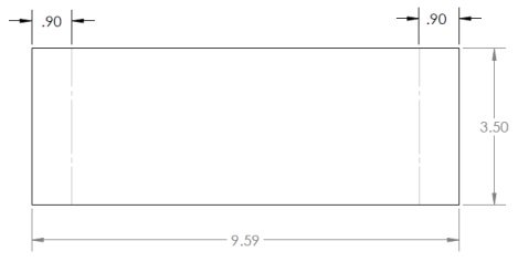
Step 3: Cut two work pieces of 0.125’’ thick mild steel sheet and drill the holes. Bend according to the guidelines (the dotted lines).
Step 4: Weld the already made parts from Step 2 and Step 3 to the frame as shown on drawing UT60x120.01.00. See montage plan (Fig. 1.6).
2. Assembling The Utility Trailer Rear Platform.
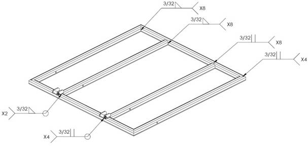 Fig. 2.1 Rear platform welding plan.
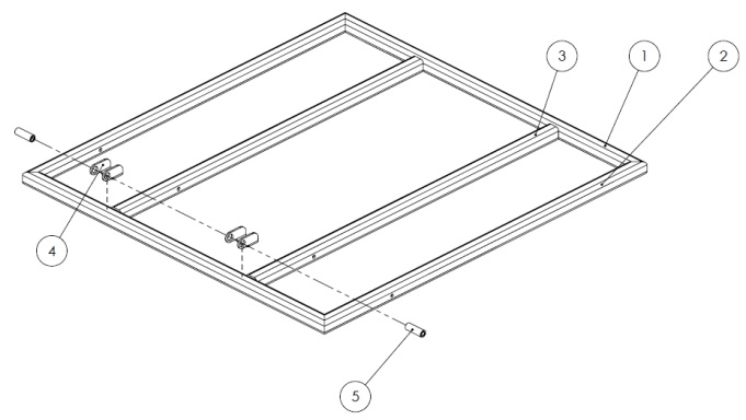 Fig. 2.2 Rear platform montage plan.
Parts:
1. Platform frame horizontal element (UT60x120.02.01).
2. Platform frame vertical element (UT60x120.02.02).
3. Inner element (UT60x120.02.03).
4. Hinge (UT60x120.02.04).
5. Bushing (UT60x120.02.05).
Step 1:
Cut part numbers UT60x120.02.01 and UT60x120.02.2 with the
corresponding length and shape the ends at 45 degrees using an angle
grinder. Drill the holes observing the dimensions on drawing
UT60x120.01.02. Lay the parts out on a flat work surface. Position them
as shown on the next figure. Tack weld them in place. Check alignment
and complete the welds according to the welding plan (Fig. 2.1).
Step 2: Cut two pieces of part number UT60x120.02.03. Arrange
them according to dimensions on drawing UT60x120.01.00. Tack weld them
in place. Check alignment again and complete the welds according to the
welding plan (Fig. 2.1).
Step 3: Cut part number UT60x120.02.04 according to the blank on drawing. Bend observing the dimensions of the guidelines. Position the parts as shown on drawing UT60x120.02.00 and complete the welds.
Step 4: Cut two 3’’ work pieces of 1’’ round bar. Turn it on a universal or CNC Lathe according to dimensions on drawing UT60x120.02.05. Put in the parts at the holes of the hinge and weld them together. See welding plan (Fig. 2.1).
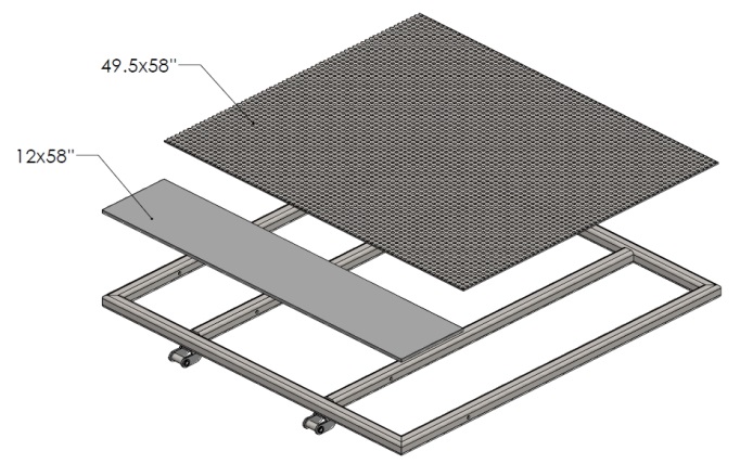
Step 5: Cut two mild steel sheet plates with dimensions and properties depending on your needs. It is recommended the upper rear platform to be perforated. Dimensions on the next pictures are examples. Fixing may be permanent (welding) or detachable (with screws).
3. Assembling The Utility Trialer.
Parts:
Chassis
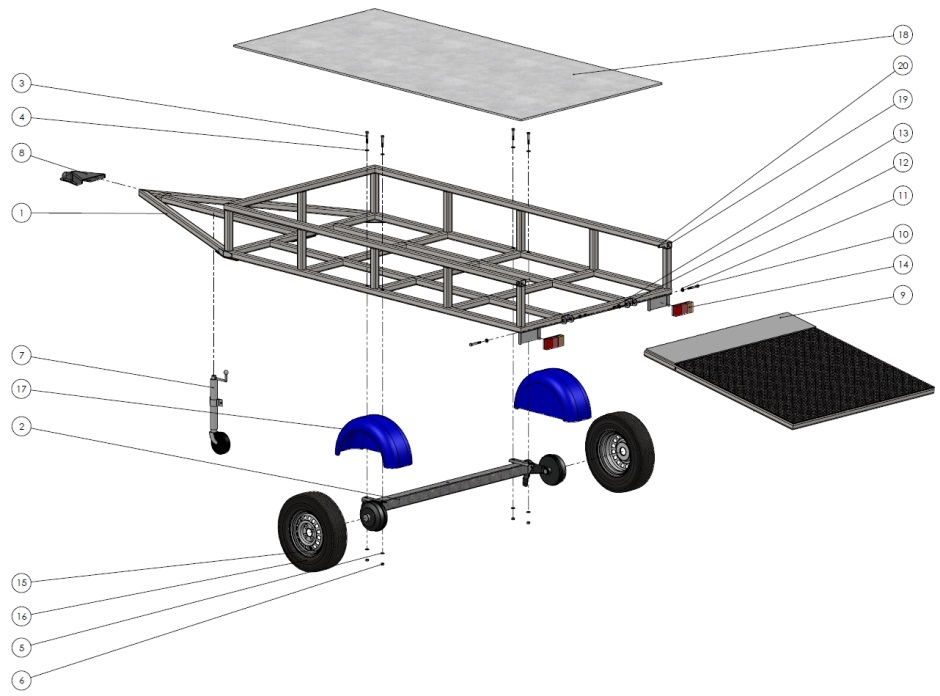
Step 1: Turn upside down the chassis frame (1) , so will be comfortable to mount the axle (2). Position the holes of the axle concentric to the holes of chassis. Thread the bolts (3) and washers (4) upside down, so when the trailer is in working position the will not fall off. Tighten using the washers (5) and nuts (6).
Step 2: Mount the supporting wheel (7) observing the dimensions
on drawing UT60x120.00.00. Turn the chassis with other components in its
normal position.
Step 3: Mount the coupling (8) to the chassis according to montage plan (3.1).
For mounting methods of supporting wheel and coupling see manufacturer’s recommendations.
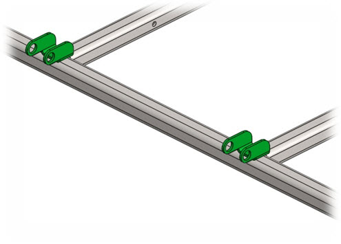
Step 4:
Position the holes of the hinges concentric and mount the Rear
door/Platform (9) using the bolts (10) and washers (11). Tighten using
the washers (12) and nuts (13).
Step 5: Mount the electric and lighting system (14) depending on manufacturer’s recommendations.
Step 6:
Lift up the chassis using a jack or crane and mount the rims (15) and
already mounted tires (16). Proceed to mounting the fenders (17).
Step 7:
Mount the floor plate (18). It could be plywood, aluminum or steel
plate according to the customer needs. Fixing may be permanent (welding)
or detachable (with screws).
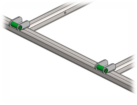
Step 8: Use pin (19) and splint (20) for fixing the rear door/platform in upright position.
Congratulations!
You finished assembling the Utility Trailer!


Welding Plans:

New! Welding Table
New! Log Splitter
Top Projects: