Build A Welding Trailer With These Step By Step Instructions!

This guide on how to build a welding trailer requires you to follow our welding trailer plans. Once you have the plans you can use this assembly guide to help you every step of the way from fabricating and welding to final assembly of the trailer.
Machinery and Tools Required For The Welding Trailer Assembly:
1. Chop saw or Angle grinder.
2. Drill press.
3. MIG, TIG or Arc Welding.
4. Welding equipment.
5. Fitter’s vise.
6. Hammer, wrench set and tape measure.
7. Drill set – 0.2’’ – 0.75’’.
8. Plasma cutter (recommended).
9. Universal or CNC lathe (recommended).
Welding Trailer Build Materials List:
1. Mild steel square tube – 2’’ X 2’’ t=0.25’’ (1760 in).
2. Mild steel rectangular tube – 2’’ X 2’’ t=0.25’’ (164 in).
3. 0.25’’ thickness (55 in2).
4. 1’’ steel round bar – (26 in).
5. (10) HBOLT 0.5-13x3.5x1.25-S.
6. (10) HJNUT 0.5-13-D-N.
7. (16) Washer narrow FW 0.5.
8. (4) Washer Wide FW 0.5.
9. (2) AL-KO braked axle U35.
10. (1) Coupling (Hitch).
11. (1) Supporting lifting leg (with wheel).
12. (4) Rim 5J15, offset 0’’.
13. (4) Tire 195/70R15.
14. (2) Fender.
15. (1) Electric and lighting system.
16. (2) Locks.
1. Assembling The Welding Trailer Chassis.
The assembling of Chassis will be discussed in two parts, because of the its big size. In the third part will be discussed the assembly of all chassis components.
Parts:
1. Drawbar element (wt144x60.01.01).
2. Drawbar element (wt144x60.01.02).
3. Crossmember, small (wt144x60.01.03).
4. Crossmember, large (wt144x60.01.04).
5. Chassis width beam (wt144x60.01.05).
6. Chassis length beam (wt144x60.01.06).
7. Inner beam (wt144x60.01.07).
8. Inner crossbeam beam (wt144x60.01.08).
9. Bushing (wt144x60.01.11).
Step 1:
Cut part numbers wt144x60.01.05 and wt144x60.01.06 with the
corresponding length and shape the ends at 45° using an angle grinder.
Drill the holes observing the dimensions on drawing wt144x60.01.06.
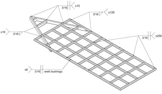
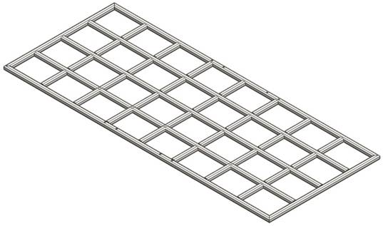
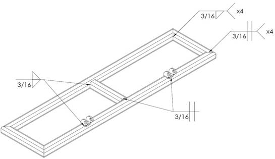
Step 2:
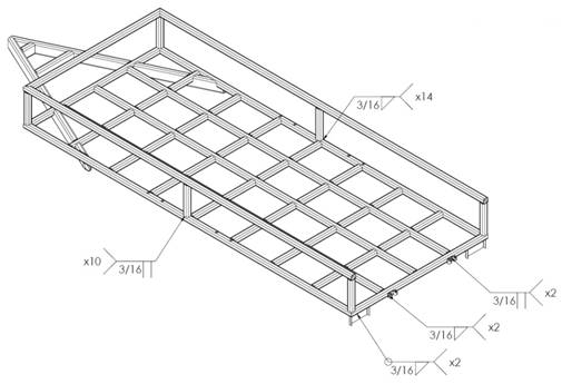
Lay the parts out on a flat work surface. Position them as shown on the
next picture and complete the welds according to the welding plan (Fig.
1.1).
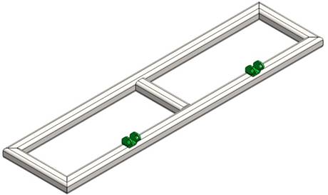
Step 3: Cut 3 pieces of part number wt144x60.01.07
and 28 pieces of wt144x60.01.08. Arrange them according to drawing
wt144x60.01.00, perform 12.5’’ dimension using inner crossbeams as
spacers. Monitor for compliance of 15.75’’ dimension. Tack weld them in
place. Check alignment twice and complete the welds according to the
welding plan (Fig. 1.1).
Step 4: Arrange the rest 20 inner
crossbeams (wt144x60.01.08) according to drawing wt144x60.01.00. Tack
weld in place. Check alignment and there is no gaps complete the welds
according to the welding plan.
Step 5: Cut part numbers
wt144x60.01.01 and wt144x60.01.02 with corresponding length. Machine the
slots according to the drawing. Note that the left and right drawbars
are different and have to be mirror machined. Position the parts as
shown and complete the welds observing the welding plan (Fig. 1.1).
Step 6:
Cut part numbers wt144x60.01.03 and wt144x60.01.04 with corresponding
length and shape the ends at 65° using an angle grinder. Position the
parts as shown on the next picture and complete the welds.
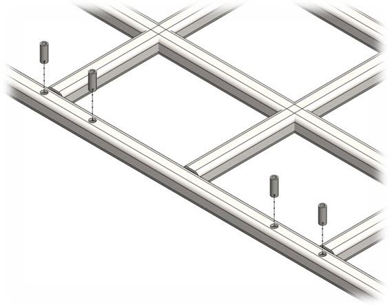
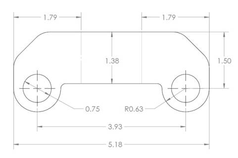
Step 7: Cut four 2’’ work pieces of 1’’ round bar. Turn it on a universal or CNC Lathe according to dimensions on drawing wt144x60.01.11. Put the parts in the holes of the side length beam and complete the welds.
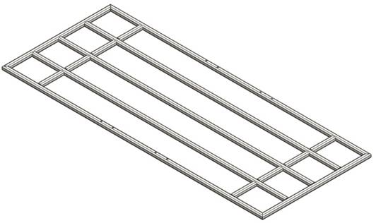
1.2 Welding Trailer Upper Frame Assembly.
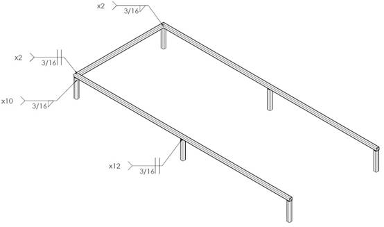
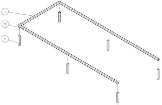
Parts:
1. Chassis width beam (wt144x60.01.05);
2. Vertical element (wt144x60.01.09);
3. Upper side beam (wt144x60.01.10);
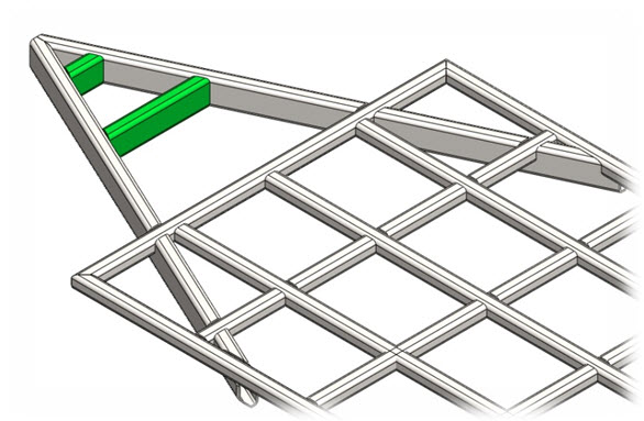
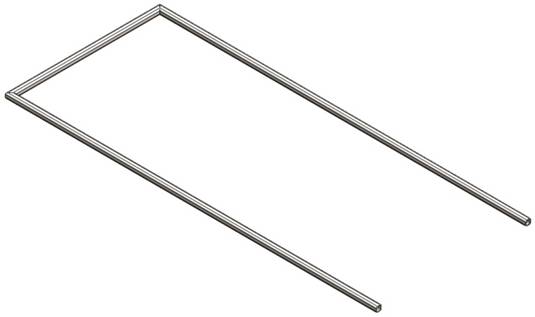
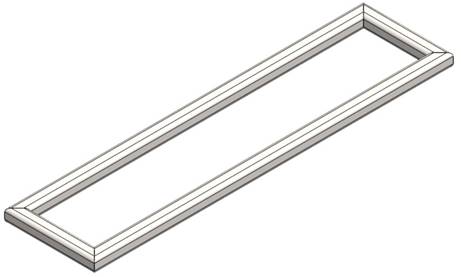
Step 1:
Cut part numbers wt144x60.01.05 and wt144x60.01.10 with the
corresponding length and shape the ends at 45° using an angle grinder.
Lay the parts out on a flat work surface. Position them as shown on the
next figure and complete the welds according to the welding plan (Fig.
1.3).
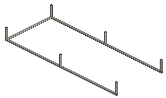
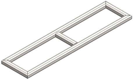
Step 2: Cut 6 pieces of part number wt144x60.01.09. Tack weld them in place one by one observing the dimensions on drawing wt144x60.01.00. Check alignment again and complete the welds according to the welding plan (Fig. 1.3).
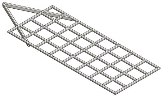
1.3 Assembling The Complete Chassis.
Parts:
1. Lower frame assembly.
2. Upper frame assembly.
3. Lower hinge (wt144x60.02.05).
4. Lights support.
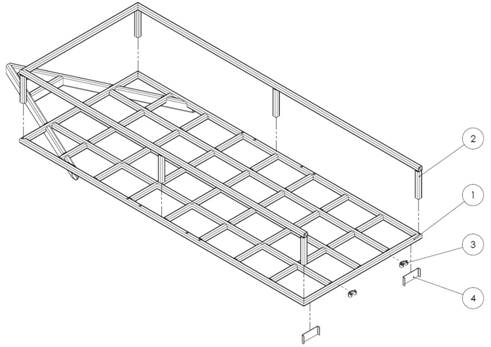
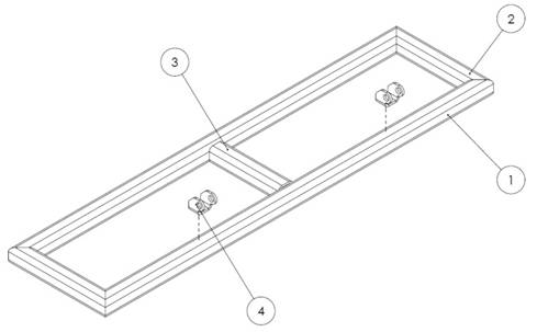
Step
1: Lay the lower frame assembly (1) on a flat working surface, so the
drawbar elements should be directed to the ground. Position the upper
frame assembly (2) according to montage plan (Fig. 1.6). Tack weld all
the connection spots. Check alignment and complete the welds according
to the welding plan (Fig. 1.5).
Step 2: Cut two 3.5x9.6’’ work pieces of 0.125’’ thick mild steel sheet. Bend according to the guidelines (the dotted lines).
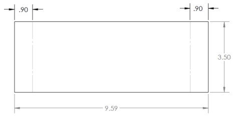
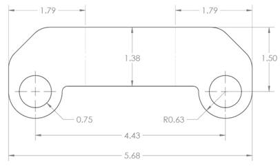
Step
3: Cut two work pieces of 0.25’’ thick mild steel sheet and drill the
holes. Bend according to the guidelines (the dotted lines).
Step 4: Weld the already made parts from Step 2 and Step 3 to the frame as shown on drawing wt144x60.01.00 and wt144x60.02.00. See montage plan (Fig. 1.6).
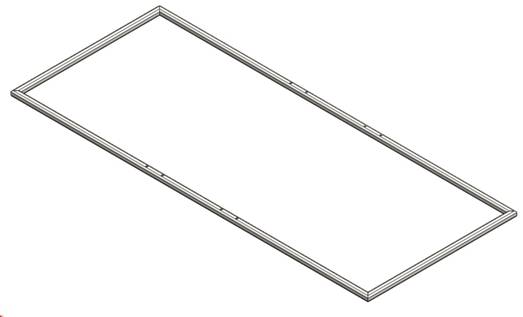
2. Assembling The Welding Trailer Rear Platform.
Parts:
1. Width element (wt144x60.02.01).
2. Height element (wt144x60.02.02).
3. Middle element (wt144x60.02.03).
4. Upper hinge (wt144x60.02.04).
Step 1:
Cut part numbers wt144x60.02.01 and wt144x60.02.02 with the
corresponding length and shape the ends at 45º using an angle grinder.
Lay the parts out on a flat work surface. Position them as shown on the
next picture. Tack weld them in place. Check alignment and complete the
welds according to the welding plan (Fig. 2.1).
Step 2:
Cut part number wt144x60.02.03 and position it in the middle of the
Width element. Complete the welds according to the welding plan (Fig.
2.1).
Step 3: Cut part number wt144x60.02.04 according to the blank. Bend observing the dimensions of the guidelines.
Step 4: Position the parts as shown on drawing wt144x60.02.00 and complete the welds.
3. Assembling The Welding Trailer.

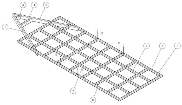
Step 1: Turn upside down the chassis frame (1), so you will be comfortable to mount the axles (2). Position the holes of the axle concentric to the holes of the chassis. Thread the bolts (3) and washers (4) upside down, so when the trailer is in working position they will not fall off. Tighten using the washers (4) and nuts (5).
Step 2: Mount the supporting leg (6) observing the dimensions on drawing wt144x60.00.00. Turn the chassis with other components in its normal position.
Step 3: Mount the coupling (7) to the chassis according to montage plan (3.1).
For mounting methods of supporting wheel and coupling see manufacturer’s recommendations.
Step 4: Position the holes of the upper and lower hinge concentric and mount the Rear panel (8) using the bushings (9), bolts (10) and washers (11). Tighten using the washers (11) and nuts (12).
Step 5: Install the electric and lighting system (13) depending on manufacturer’s recommendations.
Step 6: Lift up the chassis using a jack or crane and mount the rims (14) and already mounted tires (15). Proceed to mounting the fenders (16).
Step 7: Mount the floor plate (19). It could be plywood, aluminum or steel plate according to the customer needs. Fixing may be permanent (welding) or detachable (with screws). Mount the side plate (20), front plate (21) and back plate (22).
Step 8: Mount the locks (17, 18) using screws, or weld the parts to the frame.
Congratulations!
You finished assembling the Welding Trailer!
Recommended Articles:
Trailer Plans:


Welding Plans:

New! Welding Table
New! Log Splitter
Top Projects: